

This document describes the improvements to field calibration and diagnostics RI8535B Universal Digital TIM. It is based on the RI8535B0-80 pin digital, but can also apply to the RI8535B1-40 pin and RI8535B2-20 pin. Before August 2018, the RI8535B Universal Digital TIM was classified as only requiring calibration once in it's lifetime. Based on customer feedback and the desire to maintain NIST traceability, DC voltage calibration has been added.
Minimum Requirements
RI8525B Digital TIM in the Configuration (DPins1 - DPins4)
The following patches (or later SubVersion or Date)
GF10RC2A.172-97 Enhancements to Digital Tims (09/04/18 03:52:51 pm)
GF10RC2A.305-11 Ri8535 Deep Memory Option (09/04/18 03:46:21 pm)
GF10RC2A.306-27 Multi Bank Patterns for Ri8535 (09/04/18 03:46:55 pm)
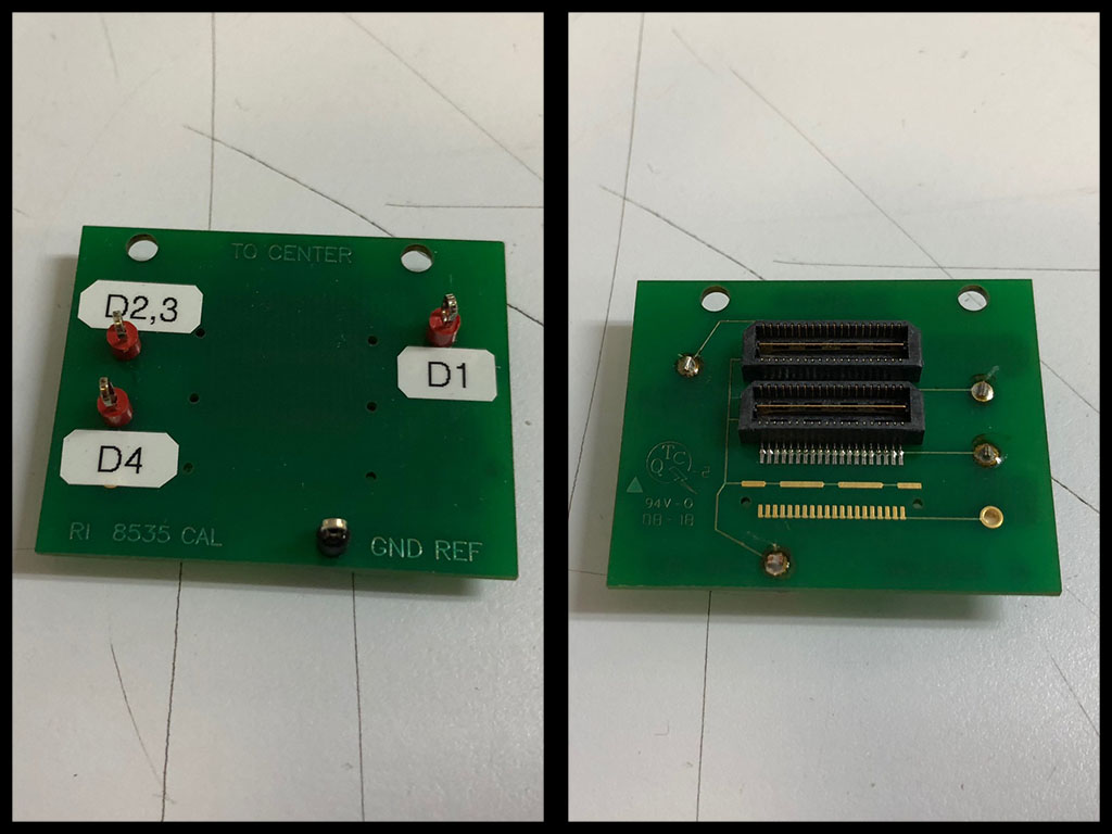
Figure 1: Digital TIM Calibration Block (Y000FAA1)
Calibration Plans:
The TIM is cal'd with a Y000FAA1 cal board. The board has all the pins in a row shorted together and brought out to a test point. Because of the spacing, Dpins2 and Dpins3 also had to be shorted together. So the test point labeled 'D1' is Dpins1-1 to 1-20. The test point labeled 'D2,3' is Dpins 2-1 to 2-20 and Dpins 3-1 to 3-20. The test point labeled 'D4' is, of course, DPins4-1 to 4-20.
The TIM must be cal'd with no fixture. Most of the plans require the cal board to be installed, but some require the board not installed. If the plan does not specifically say otherwise, assume the cal board should be installed.
2) With no fixture installed, install the cal board onto the digital TIM.
3) The cals are run using the cal list 'RI8535B0 Digital 80 Pin Factory Cals'. Open this list through the configuration panel's 'System' instrument.
As of 2018-09, the cals in the list are:
RI8535B Dpins1 Calibration
RI8535B Dpins1 Validate
Ri8535B Dpins1 timer pin delay verify
RI8535B Dpins2 Calibration
RI8535B Dpins2 Validate
Ri8535B Dpins2 timer pin delay verify
RI8535B Dpins3 Calibration
RI8535B Dpins3 Validate
Ri8535B Dpins3 timer pin delay verify
RI8535B Dpins4 Calibration
RI8535B Dpins4 Validate
Ri8535B Dpins4 timer pin delay verify
Ri8535B0 80 pin Digital Pins Verify
Ri8535B Pattern Load Test Reminder
4) Run the cals in order, following the instructions. The DPins1, 2, 3, and 4 cals are straightforward.
The 'Ri8535B0 80 pin Digital Pins Verify' is a special verify that clears any existing patterns and loads a pattern called 'Pins Test'. Pins Test is a travelling 1's pattern designed to test for any shorts between pins. Since the cal board shorts pins together, it must be removed for this test.
The 'Ri8535B Pattern Load Test Reminder' is not an actual test. It is a reminder that further tests must be done outside of any test plans.
5) To test the integrity of pattern loading, perform the following:
a) Make sure that the 'messages' panel is open.
b) In the configuration window, highlight DPins1. In the lower left corner is a button labeled 'Edit Patterns'. Click it to open the 'Editing Patterns' window.
c) There should be only 1 pattern listed, 'Pins Test'. Highlight it, RMBC, and select 'Test'.
d) After the test is run, note the messages panel. The checksum labeled 'expect' and the checksum labeled 'meas' should be the same. If they are the same, the test passes.
e) Close the 'Editing Patterns' panel.
f) Repeat this process for DPins2, 3, and 4.
6) After the calibration is complete, open the 'Diagnose' list and run them.
As of 2018-09, the plans in the list are:
RI8535B Dpins1 Verify
RI8535B Dpins2 Verify
RI8535B Dpins3 Verify
RI8535B Dpins4 Verify
Note that these plans can be run with the cal block installed or not installed, either way.
The RI8535B0 digital TIM is now calibrated.